How to Wire Dometic or Norcold RV Fridge Video
This page and video breaks down the Fridge Defend by ARP wiring into easy to understand steps by teaching how the ARP works using simple examples.
REQUIRED TO DOWNLOAD INSTALLATION INSTRUCTIONS - WEB PAGES ARE SUPPLEMENTAL - EACH VERSION OF CONTROL HAS INTRICACIES REQUIRING THE WRITTEN INSTRUCTIONS.
Table of Contents
Instructions: Subjects are listed on left. Click the link to the right to go directly to the subject matter on this page.
- How Switch Works ARP is Switch
- ARP Automatic Switch ARP is Automatic
- ARP and Your Fridge Fridge Control
- ARP Limits Boiler Temp Protecting Fridge
- ARP Boiler Sensor Safe Boiler
- Basic Wiring Video See How to Wire

How ARP is Wired -- ARP is like a Switch
The ARP Control is very easy to wire once one knows how the ARP works.
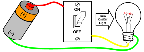
The first step is to understand that the ARP is no different than a switch. The first drawing shows the wiring required to power a light bulb. The green ground wire is connected directly between the battery and the light bulb. The positive side of the battery has a switch that turns on and off the light bulb. The red wire sends power from the battery to the switch. The yellow wire is the switched power wire. When the switch is turned on the power from the red wire is connected to the yellow wire and the light bulb lights up.

House Thermostat is an Automatic Control
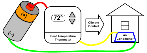
The switch above needs a human to toggle the switch on and off to control the light bulb. This drawing shows a battery and a thermostat which controls the household temperature. The thermostat turns on the power to the air conditioner automatically if the temperature inside the house is not 72 degrees. Thus, the thermostat is just an automatic switch.
The ARP Control is a thermostatic automatic switching device.

The Dometic or Norcold Control and Your Fridge
The next step is to replace the battery with your RV and its power supply.
We
replace the thermostat above with the Dometic or Norcold control. The
house is replaced with the fridge because the Dometic or Norcold control
keeps the temperature constant in the fridge just like the
thermostat for the house.
Please note that the red wire supplies power to the
Dometic or Norcold
control, your RV may have different color wiring so use a DMM to
locate power and ground. When the fridge needs cooling, all the
fridge control does is switch on a heat source which in turn
powers the cooling unit.

The Fridge Defend by ARP Controls the Fridge by Switching Power to the Fridge Control Box
This drawing replaces the fridge with the fridge controller.
Your RV has a power and ground that supply the energy needed to
run your fridge controller as seen in the above drawing.
Because the ARP interrupts power to the fridge
just like the light switch in the first drawing, or the
thermostat in the second drawing, the ARP must be wired inline
with the 12 volt power supply from the RV to the fridge control.
The ARP Control is simply wired in-line with the
12 volt power wire going to the Dometic or Norcold control box.
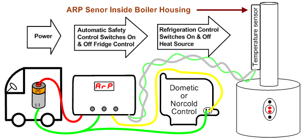
The ARP red wire will connect to the RV +12V power supply.
The ARP yellow wire will deliver the +12V power to the Dometic or Norcold fridge control.
If your fridge cooling unit overheats the Fridge Defend will switch the power off between the ARP red wire and yellow wire, then automatically restart the fridge when the boiler cools.

Just add the Boiler Temperature Sensor to Complete
The final drawing shows all of the components needed for the wiring of the ARP Control. The cooling unit boiler is shown to the right. The boiler drawing shows the boiler tube with the insulation removed. The ARP boiler temperature sensor is clipped to the boiler tube. When the cooling unit boiler overheats the ARP turns off the power to the Dometic or Norcold control thereby turning off the cooling unit heat source.
It must be emphasized that this is an install overview. For example, if your RV fridge has a recall, it will be inline with the power supply just like the ARP Control. These drawings do not show the recalls, and it is the end user's responsibility to insure that all recalls remain functioning after the ARP has been installed. Please reference the menu above for further ARP documents needed for an install and the operation of the ARP Control.
Basic Wiring Video
Now that the basic wiring for the Fridge Defend is understood, this is a simple overview of how the Fridge Defend is installed on either a Dometic or Norcold fridge.
1) Find and remove the fuse before working on any electrical wiring.
2)
If your fridge circuit has greater than a 5 amp fuse on the refrigerator circuit please put a 5 amp
Circuit Breaker (Click Here)
on the ARP red wire.