The Fridge Defend by ARP will keep your Norcold Models 600, 6000, 6100 alive for many more years.
REQUIRED TO DOWNLOAD INSTALLATION INSTRUCTIONS - WEB PAGES ARE SUPPLEMENTAL - EACH VERSION OF CONTROL HAS INTRICACIES REQUIRING THE WRITTEN INSTRUCTIONS.
Before reading this page, please click here and view our wiring video.Instructions: Subjects are listed on left. Click the link to the right to go directly to the subject matter on this page.

This drawing shows the view looking into the vent door at a 600 or 6000 series fridge. These refrigerators were exceptional RV fridge, the number of units still in operation attests to this fact. To keep these excellent refrigerators alive it is recommended to keep the boiler of the fridge from overheating with the Fridge Defend by ARP. This page is an overview of how to install the ARP.

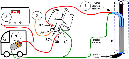
We do not recommend using the 12VDC (3rd-Way) for cooling your fridge because the 12VDC heater can destroy the fridge if the Fridge Defend by ARP is not protecting the fridge. If the Fridge Defend is being used to control boiler temperature, it is not unusual for the controller to trip due to the 12VDC heater. One can just disconnect the 12VDC heater if you choose not to use it, otherwise click on the following link for wring a load relay:
Please click this link for wiring on the 3-Way fridge models.
This photo shows a Norcold 6182 with the door to access the electric heaters opened to install the boiler sensor.
The red arrow points to the cooling unit boiler tube at the approximate location where the Fridge Defend boiler sensor will be installed. On this cooling unit the flue tube is behind the boiler tube, this makes the installation on the 600, 6000, & 6100 series very easy. Please make sure the temperature sensor is insulated as per the example on the Boiler Temperature Probe Install page.
The yellow arrow points at the slot where the cooling unit heater access door tab is engaged. Press the housing together to disengage the door latch.
The orange arrow points to the electric heating element, the electric heating element is always attached to the cooling unit boiler tube.

This photo shows the Fridge Defend boiler sensor clipped onto the boiler tube. The insulation is placed under the ARP boiler sensor wire, the wire should also be wrapped with insulation where it exits the boiler housing to keep the sheet metal from cutting it. The entire sensor shall be insulated so that ambient air cannot enter the boiler housing.
Please note that all of the following specifications are believed to be accurate. If any errors are found, please bring them to our attention as soon as possible. For critical specification please contact Norcold as they make changes to their specifications without notice.
| Item | Value | Units |
|---|---|---|
| ARP Control Boiler Temperature | See Note 1 Below | |
| Off-Level Operating Limit | See Note 2 Below | |
| AC Heater | 1.7 | Amps @ 120VAC |
| AC Heater | 70.5 | Ohms +/-10% |
| DC Heater | 9.2 | Amps @ 12VDC |
| DC Heater | 1.3 | Ohms +/-10% |
| Temp Setting Range | 1 - 5 | 5 = Coldest | See Note 3 Below |
| Item | Value | Units |
|---|---|---|
| ARP Control Boiler Temperature | See Note 1 Below | |
| Off-Level Operating Limit | See Note 2 Below | |
| AC Heater | 2.9 | Amps @ 120VAC |
| AC Heater | 41.3 | Ohms +/-10% |
| DC Heater | 13.8 | Amps @ 12VDC |
| DC Heater | 0.07 | Ohms +/-10% |
| Temp Setting Range | 1 - 5 | 5 = Coldest | See Note 3 Below |
NOTES
Note 1: 185-195°C - 365-383°F
Note 2: Dependent on ambient and ARP boiler temp.
Note 3: Thermistor Values
If you cannot find what you need please use the Contact Us form on the top menu.