If you do not have the ARP Control you are not protected. This page shows how to install the ARP Control and gives service manual specifications for troubleshooting and repair of Norcold 2118 PolarMax fridges.
This page is intended to supplement the installation documentation and is not considered to be complete.
REQUIRED TO DOWNLOAD INSTALLATION INSTRUCTIONS - WEB PAGES ARE SUPPLEMENTAL - EACH VERSION OF CONTROL HAS INTRICACIES REQUIRING THE WRITTEN INSTRUCTIONS.
Instructions: Subjects are listed on left. Click the link to the right to go directly to the subject matter on this page.

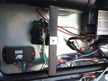
The first photo is of the ARP Control installed on a 2118 PolarMax in a Montana 5th Wheel trailer. Please note that the Norcold 2118 cooling unit compartment has plenty of room for mounting the ARP. It is desirable to mount the control on the metal plate as seen in this photo. Velcro Industrial tape was used to attach the ARP to the metal plate. The screws that come with the ARP can be use also.
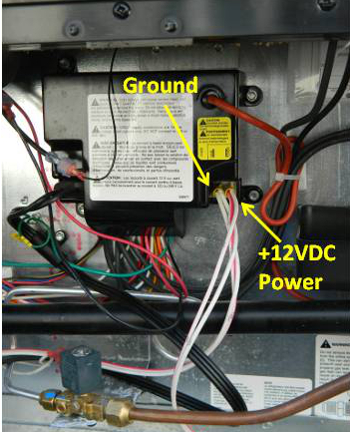
The next photo is a close-up of the 2118 refrigeration controller. The +12VDC power and ground are identified. The wiring procedure is straight forward for this control. The +12VDC power wire will be removed from the Norcold control and connected to the ARP red wire. The ARP should be grounded at the Norcold control ground wire.
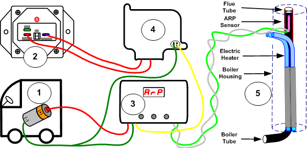
Please view the drawing below for the following step by step instructions:

The following two photos show how to wire the ARP. The second photo on this page shows the RV power supply wires entering into the cooling unit compartment and going to the Norcold control. The drawing after shows how the ARP will appear after fully wired.
(1) On this RV, the ground wire is white and the +12VDC wire is white with a red stripe. The colors of the wires on your RV are dependent on the manufacture. The first step is to identify the correct wires delivering power to the fridge.
(2) This is the Norcold recall, please see this page for more information on the function of this recall: Norcold Recall Function

(3) This shows how the power coming from the RV goes to the ARP red wire, and the ARP yellow wire being connected at the location on the Norcold control where the RV +12VDC was disconnected.
(4) Norcold control box as seen in second photo on this page, with the exception that the power is now coming from the ARP control.
(5) To make the wiring complete the ARP boiler temperature sensor is shown within the boiler housing on the boiler tube. Please see the next section for the installation of the boiler sensor.

This photo is of a Norcold 2118 boiler tube with the ARP temperature sensor being clipped on. The sensor needs to be approximately an inch above the heating elements at minimum. The sensor should not be higher than the second from top absorber coil, which is very hard to reach if the fridge is installed in the RV.
Once the ARP sensor is installed correctly, please see installation instructions, the sensor should be insulated with fiberglass insulation so that it only reads the boiler tube temperature.
Often the boiler needs to be insulated where the gap in the factory insulation is. If this gap is open, cool air will enter the boiler housing and reduce the efficiency of your fridge.
| FAULT CODE | MEANING | POSSIBLE SOLUTION |
|---|---|---|
| No Display | No 12VDC to Fridge. |
Make sure fridge is on.
Check power and ground at Norcold Control board. ARP Control detected an overheat situation, check ARP display to see if a count down period tells when control will turn back on fridge. Check under control board cover Fuse F1. Check Norcold recall, if LED on, click here for reset. |
| no AC | The shore power is less than 85VAC. This fault only occurs while operating in the AC Mode. If in Auto Mode this code is displayed with other codes such as flashing 'no FL'. |
Check power cord for shore power and at fridge.
Click here for AC safety and GFI receptacle. Fuse F2 under Norcold control box cover blown, click here for fuse type. |
| no FL | LP flame did not light. This fault is only present when in the Gas Mode. This fault will be presented with other faults if in the Auto Mode. |
Remove LP burner cover, check electrode gap,
clean burner, check wiring and ground for
LP igniter.
Click here for igniter adjustment. Turn off fridge and restart. Check LP Gas pressure and electrode gap. Click here for gas valve and igniter check. |
| FL -- | LP flame on when there should not be. | This can be from either a stuck open gas (SOV) valve, or the relay in the controller stuck shut and power is activating the SOV. |
| no AC ↔ no FL |
Two faults occurred: The controller sensed the AC input voltage to be less than 85VAC. When above condition was sensed, the controller switched to LP Gas Mode and a flame was not sensed. | Please see the combined above faults and use the information there for solutions. |
| AC HE | AC Heater current low. |
AC heaters failed.
Click here for improved AC heater safety. Click here for AC heater troubleshooting. |
| AC rE | AC heater relay is stuck closed. | Try cycling the fridge on/off. Open cover for power board and tap on AC relay to see if can free up. |
| oP LI | Norcold recall has tripped, caution needs to be exercised. |
This code requires caution due to the nature of
the Norcold recall black box. These black box
can false trip, or if they do trip due to
overheat, there is a dangerous situation
that may need to be addressed.
Click here to understand the need for the ARP Control & why 800F is just too hot for black box trip point. Click here for reset procedure and testing of cooling unit. Click to see Norcold 1200 series recall for further info. |
Please note that all of the following specifications are believed to be accurate. If any errors are found, please bring them to our attention as soon as possible. For critical specification please contact Norcold as they make changes to their specifications without notice.
| Item | Value | Units |
|---|---|---|
| ARP Control Boiler Temperature | See Note 1 Below | |
| 2118 Total Volume | 18 | cu. ft |
| 2118 Freezer Volume | 5.9 | cu. ft |
| Off-Level Operating Limit | See Note 2 Below | |
| Temp Setting Range | 1 - 9 | 9 = Coldest | See Note 3 Below |
Fuses
| Item | Value | Units |
|---|---|---|
| Board 12V Fuse | 5A | Amp |
| 120VAC | See Note 4 Below | Amp |
DC Power
| Item | Value | Units |
|---|---|---|
| Divider, Flaper, Perimeter Heaters | 0.967 | Amp |
| Interior Light | 0.5 | Amp |
| Gas Valve | 0.146 | Amp |
| Ice Maker Heaters | 1.875 | Amp |
| Fans | 1 | Amp |
| Total Amp Draw | 4.342 | Amp |
AC Power
| Item | Value | Units |
|---|---|---|
| Operating Range | 108 - 132 | VAC |
| AC Heaters | 300 / 2.5 | Watts / Amps (per heater) |
| AC Heaters | 46 - 51 | Ohms (per heater) |
| Measurement Conditions | 120 | VAC |
LP Gas
| Item | Value | Units |
|---|---|---|
| Gas Pressure | 10.5 - 11.5 | inch w.c. |
| Heat Input | 3000 | BTU/hour |
| Gas Jet | LP22 | |
| Burner | 8-slot | |
| Electrode to Burner Gap | 1/8" to 3/16" | inch |
2118 NOTES
Note 1: 185-195°C - 365-383°F
Note 2: Dependent on ambient and ARP boiler temp.
Note 3: Also see thermistor location, second fin from right at this link:
Thermistor Troubleshooting
If the thermistor has failed, put the fridge control onto the fridge temperature display mode.
If the display flashes, the thermistor may have a bad connection or need to be replaced.
Please see thermistor tables below.
Note 4: AGC Series, 8A, Fast Acting.
| Temperature (F) | Temperature (C) | Approximate Resistance (kOhms) |
|---|---|---|
| 32 | 0.0 | 30 - 32 |
| 33 | 0.6 | 28.5 - 29.5 |
| 35 | 1.7 | 24.5 - 25.5 |
| 40 | 4.4 | 22.5 - 23.5 |
| 50 | 10.0 | 15.5 - 16.5 |
| 60 | 15.6 | 12.1 - 13 |
| 75 | 23.9 | 10.1 - 11 |
| 80 | 26.7 | 9.1 - 10 |
| 85 | 29.4 | 8.1 - 9 |
If you cannot find what you need please use the Contact Us form on the top menu.