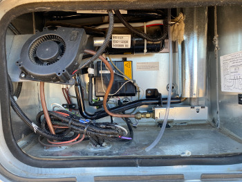
Dometic has introduced a new series of refrigerator for 2019, the 10.5 series. This is an absorption refrigeration system that requires the Fridge Defend to remain reliable and safe.
REQUIRED TO DOWNLOAD INSTALLATION INSTRUCTIONS - WEB PAGES ARE SUPPLEMENTAL - EACH VERSION OF CONTROL HAS INTRICACIES REQUIRING THE WRITTEN INSTRUCTIONS.
Instructions: Subjects are listed on left. Click the link to the right to go directly to the subject matter on this page.

The new Dometic series of RV refrigerator breaks with their traditional model number scheme. For example, the excellent RM series of fridge made for 30 years told you the refrigerator capacity in cubic feet (cuft) in the model number. Dometic's 10.5 series is not a 10 cubic foot fridge, they are 5.4 and 6.3 cubic feet respectively.
Click here to see how the Fridge Defend by ARP helps prevent boiler overheat situations.
This photo shows the Fridge Defend installation on a Dometic RMD 10.5 XT fridge. The insulation is the same as other 6 cubic foot domestic refrigerators. The Fridge Defend not only added safety to this fridge, it improved its performance due to the added ventilation with the v5.1 fan controller kit.

| Plug ID | Wire Description |
|---|---|
| A | Power to Dometic Controller |
| B | D+ Engine Alternator |
| C | +12VDC Heater |
| D | Ground to Dometic Controller |
| E | No Connection |
| F | Ground DC Heater |
Use this drawing to wire the Fridge Defend with the Dometic 10.5 fridge. Note that the wires are identified in the plug end for the wires going to the fridge. The purple wire in position 'A' supplies power to the Dometic controller. The purple wire should have a 3 amp fuse in it, and this is the wire that is spliced for the Fridge Defend insulation.

| Item # | Item |
|---|---|
| 1 | Fan 2 |
| 2 | Fan 1 |
| 3 | S+ (optional) |
| 4 | DC Heater |
| 5 | DC Heater Relay (10A fuse) |
| 6 | 4.2 |
| 7 | Thermistor 1 (fridge) |
| 8 | Gas Valve |
| 9 | AC Heater |
| 10 | LP Burner |
| 11 | Connector Block |
| 12 | Lighting |
| 13 | Display |
| 14 | Heating Frame |
| 15 | Fan 2 (optional) |
| 16 | Fan 1 (option) |
| 17 | Options Module |
| 18 | DC Supply Oven (optipn) |
| 19 | DC Options Module |
| 20 | CI-Buss Connection |
| 21 | DC Power Supply |
| 22 | 12V Terminal Housing |
| 23 | DC Supply Cable Electronics |
| 24 | DC Supply Heating Element |
| 25 | Internal DC Supply (Max 1A) |


Once the bottom plate is removed, squeeze the boiler housing to unhook the seam that runs up the housing. This photo shows the Fridge Defend boiler sensor installed just above the electric heaters on the boiler tube.
The fiberglass insulation, GREEN ARROW, packed between the flue tube and the sensor prevents the heat from the flue tube from getting to the boiler sensor.
The sensor can be mounted closer to the heaters (RED ARROW). If sensor is close to the heaters please insulate the sensor very well.
Wrap fiberglass insulation around the Fridge Defend sensor wires (PURPLE ARROW). If these wires are not protected, the sheet metal can cut the wires.
| Item | RMD10.5T | RMD10.5XT | Units |
|---|---|---|---|
| Dimensions - Depth | 21.7 | 23.8 | inch |
| Dimensions - Height | 49.1 | 49.01 | inch |
| Dimensions - Width | 20.6 | 20.59 | inch |
| Weight | 88.2 | 91.5 | lbs |
| Volume - Total | 5.4 | 6.3 | cubic-feet |
| Volume - Fridge | 4.2 | 4.8 | cubic-feet |
| Volume - Freezer | 1.0 | 1.23 | cubic-feet |
| 12VDC Heater Input Current | 14.2 | 14.2 | Amp |
| 12VDC Heater Input Power | 170 | 170 | Watts |
| AC Input Power | 250 | 250 | Watts |